There are many descriptions of what the process entails ranging from those that are highly technical to those that are extremely simplistic. For the purposes of this article we will try to steer a middle course.
WHERE ARE ELECTROPLATED COATINGS USED?
Electroplating finds a wide variety of uses. Generally it enables the design engineer to combine the desired features of the base metal with additional surface properties provided by a different metal. By far the biggest call is for the coating of items manufactured from steel. This is because steel is a strong hard material with a high melting point that is plentiful and relatively inexpensive. It can be rolled into sheets, bent or cut into strips from which parts may be punched out using purpose built tools. It can be machined, cast, drawn into rods and wire. In short, it is extremely versatile, and thus used in thousands of applications.
On the downside, steel is highly susceptible to rust and without some form of protection against corrosion, components manufactured from steel would have a much shortened life expectancy. Zinc is an ideal coating to extend the service life of steel components and remains the most commonly plated metal.
Electroplating is vital in the following sectors: Automotive Industry, Maritime Industry, Consumer Durables, Recreational Goods, Aerospace, Machine Tools, Hydraulic Equipment, Electronics, Jewellery and Medical.
Electroplating is a wet chemical process consisting of a series of tanks usually laid out sequentially, typically in a straight line or a horse-shoe configuration, with each tank having a very specific purpose. The process may generally be divided into three distinct phases (with thorough rinsing between each stage) as follows:
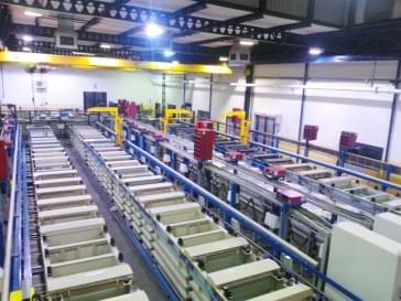
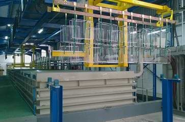
One of the many modern turnkey plating plants installed by Accurate Automation and Consulting
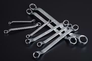
Chrome plated spanners
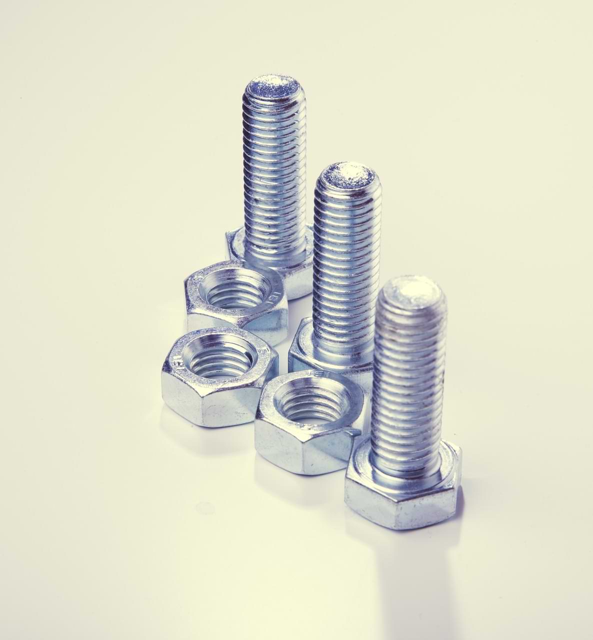
Zinc plated bolts and nuts
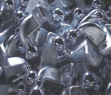
Zinc plated tow bar fittings
THE BASIC LAYOUT OF AN ELECTROPLATING PLANT

Complete Nickel Chrome plating line including pre-cleaning stages prior to plating stations.
THE PRE-CLEANING STAGES
Alkaline Hot Soak De-Greasing and Electro-cleaning: This is the first stage of the plating line. Oils/soils/grease are removed by immersion for a period of time in a specially formulated solution that will contain alkaline builders and detergents at the right concentration and at the right temperature to suit the requirement. Sometimes this step is followed directly by immersion in a similar solution, but where the hot soak bath is configured as an electrolytic cell so that when the current is applied the work-piece is bombarded with hydrogen which tends to accelerate the removal of soils by the "scrubbing action". In certain instances this Electro-Clean solution will be postitioned further down the line, post acid cleaning, to bounce off soils like welding scale loosened in the acid cleaning step.
Acid Pickling: Once all the greases/oils and soils have been removed in the alkaline cleaning tank, the work-pieces need to be immersed in a dilute acid solution to remove any oxidation present on the surface. Oxides can be present in various forms like mill scale, or surface rust. Even if the metal appears to be bright and clean, oxide will still be present and must be removed prior to plating. In fact about 0.25 micron of the material surface must be physically removed in the acid to provide an absolutely virgin surface for the electroplated deposit to key into. The electroplating bond relies on diffusion of the plated deposit into the substrate and vice versa. Anything that impedes this bond will compromise adhesion and failures may present immediately or emerge later when the plated component is subjected to any form of stress.
THE PLATING TANK - ELECTROLYTIC CELL CENTRAL TO THE PROCESS
In an electroplating workshop the plating bath or tank where actual deposition takes place is, technically speaking, an electrolytic cell. The components of the electrolytic cell are all of equal importance, and in the absence of any one of them, the process cannot work. Plating tanks can be tiny or gigantic in size, depending on the configuration and required throughput of the components that require plating.
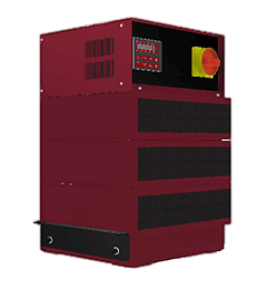
Tanks will always be hooked up to a source of direct current to drive the electrolytic process. This is provided by a transformer/rectifier unit connected to the mains supply. In the plating shop, this is commonly referred to as the rectifier. (because it converts alternating current from the mains to direct current needed for plating - it rectifies the alternating current)
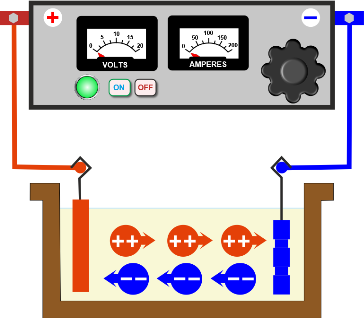
THE ELECTROLYTIC CELL- A SCHEMATIC DIAGRAM DETAILING THE COMPONENTS
The DC power source referred to as the rectifier is shown at the top. The positive terminal leads to the anode (coloured red) and the negative terminal to the cathode (coloured blue) The ions in solution are represented as spheres - Red spheres are the positively charged cations moving towards the cathode, blue coloured spheres are negatively charged anions moving towards the anode. Cations convert to metal atoms when they reach the cathode and form the metallic deposit.
The primary components that have to be part of this tank are as follows:
In most systems the anodes dissolve during the plating process, replenishing the metal that is depleted from the solution as it is plated onto the cathode. However, in some systems, notably chrome plating, the anodes are inert and do not dissolve, serving only to provide current to the electrolytic cell. In this case they are fashioned from a lead alloy, but inert anodes for some processes may be fashioned from mild steel, stainless steel, carbon or platinised titanium depending on the specifications for the solution where they will be used.
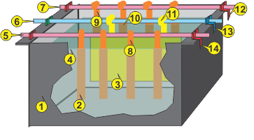
A 3-D VIEW OF A BASIC PLATING TANK
Tap or click drawing for detailed key
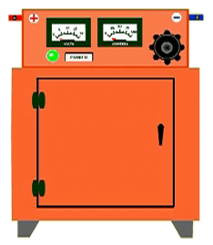
Basic Sketch of a 3 Phase Rectifier
ADDITIONAL CONSIDERATIONS IN ELECTROPLATING TANK DESIGN
Agitation: Some solutions require vigorous agitation to refresh the concentration of ions in the immediate vicinity of the work piece and/or to bounce off hydrogen bubbles that attach to the face of the work piece during the process. This can be achieved via a blower unit driving air into a correctly designed sparge at the bottom of the tank. Alternatively, and preferably, an educator system driven by a dedicated pump will accelerate solution through strategically placed eductors directing a strong current of solution towards the work.
Construction: The material of construction will generally be a plastic such as polypropylene (and where steel reinforcement is called for, this will be encased in polypropylene) if we are talking about a custom built unit from a professional plant builder. In the case of solutions running at an acid pH such as acid copper plating, acid nickel, or acid tin plating a plastic construction is absolutely necessary. Some plating solutions are alkaline and such solutions can operate in tanks fabricated from steel. However, this is not desirable as steel tanks in a plating shop will corrode on the outside due to the nature of the process, and so it is common practice to fabricate all tanks on a plating line from polypropylene.
Heating: If the solution has to operate at elevated temperature, then heaters and thermostat control will be incorporated. In addition a heated tank needs to have a level controller that shuts off the heater should the solution level evaporate (without automatic replenishment) to the extent that overheating of the element may set fire to the tank. Sheaths of heaters have to be manufactured from material that will stand up to the particular chemistry of the solution. For instance, a stainless steel heater will not be suitable for use in an acid copper plating solution running at very low pH.
Air Quality Management: During the plating process fine hydrogen bubbles are generated. When these escape into the surrounding air they carry with them small amounts of actual process solution. The fine mist that develops over the plating tank during the plating process is actually an aerosol of plating solution. Depending on the process and the illumination of the work area, in some cases it may not be readily visible. However, in others, like chrome plating, in the absence of fume management, a choking thick brown fog will be very obvious around the tank, and be dispersed around the room. The heavier the workload on the tank, the greater will be the generation of fumes.
Such mists escaping into the area where the operators are working will always present a health risk, and one or another system must be incorporated to protect them against exposure. This subject will be revisited in a page planned for inclusion under the heading "Options for coping with Fume Generation".
THE CRITICAL IMPORTANCE OF WATER IN THE PLATING PROCESS
Running Rinses and Recovery Rinses: Following each of the stages described above it is necessary to thoroughly rinse work-pieces as they move through the line. This is to be sure that whatever was loosened in the particular cleaning process gets washed off before the part moves into the next phase. The same applies to the actual plating process - the work must enter the tank absolutely clean, and then when it moves out of the plating tank, all traces of plating solution must be removed before any post-plating process can be applied. In particular multiple rinses are essential following plating processes. The first of these should always be a static rinse also referred to as a saver rinse or dragout tank where the greater amount of solution dragged out of the plating tank is retained and can be returned to the plating tank to top up and replenish the dragged out losses.
Managing water use in the Plating Shop: It can be deduced from the foregoing that there will be a significant number of rinse tanks on the plating line and water is a major resource in the plating process. In a world where water scarcity is a reality in many geographical areas, the management of water is demanding greater attention. We can also not afford to allow diluted plating solution to be carried away in sewers to the municipal water treatment system where it hampers recovery of grey water and makes sludge unusable for agricultural use.
Effluent Treatment is Compulsory: One of the expenses often underestimated, particularly by operators who elect to build their own plants at low cost, is that of providing an effluent treatment facility. This can turn out to be a serious misjudgement as every jurisdiction has strict by-laws in place detailing the maximum prescribed limits for contaminants in effluent. This includes pH, conductivity, heavy metals measured in ppm, other toxic discharges and more.
A more detailed overview of effluent treatment will be included on this website in planned future updates.
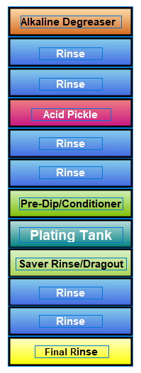
BASIC TYPICAL PLATING LINE LAYOUT HIGHLIGHTING RINSE CONFIGURATION
RACK PLATING VERSUS BARREL PLATING
When the components to be plated are suspended individually on appropriate hooks (jigs) or on purpose built frames incorporating multiple suspension points we refer to the process as rack or jig plating. Jigs populated with work-pieces are suspended from the cathode rail, so that the items to be plated are fully immersed in the electrolyte.
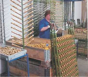
Workpieces being attached to jigs for conventional rack plating
However, if the parts to be plated are small enough to tumble freely against each other in a rotating barrel, and it has been established that they will not damage each other, nor get jammed into each other or stick to each other then barrel plating is a quick and efficient method to process these.
A plating barrel is a sturdy plastic drum, usually hexagonal in shape, with each face of the hexagon perforated with hundreds of small holes to allow solution to flow freely through the barrel, and with it charged metal ions. One of the faces of the hexagon is a removable panel, the barrel door, through which work-pieces are loaded for plating and unloaded after. The door is securely closed during the plating process.
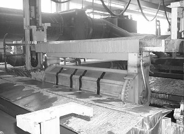
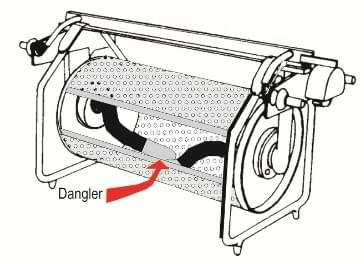
Diagram of a small plating barrel showing the loose swinging contacts (referred to as danglers) inside the barrel that transfer the negative charge onto the workpieces
A large plating barrel - the alternative to jig plating is used when parts are suited to bulk processing
The barrel frame incorporates contact blocks that pick up the current from matching contact blocks on edges of the plating tank. Various methods are used to conduct the current from the barrel contact points to thick, flexible, insulated cables (typically welding cable) that protrude through a centre hole in the plastic bearings on which the barrel rotates. These flexible contacts terminate in machined end pieces that make contact with the metal parts that are cascading against each other, under the solution, as the barrel rotates. This completes the circuit between the anodes and the work-pieces causing the metal surface coating to deposit.
Depending on the size and configuration of the items for barrel plating, and the design and size of the barrel itself, hundreds or thousands of parts can be plated at once. Barrel plating obviously does away with the need for individual handling of components while jigging and de-jigging saving on time and labour costs. Whilst barrel plating takes considerably longer to build up the deposit thickness required, the fact that huge quantities can be handled at once, in multiple barrel stations if necessary, makes this form of plating the method of choice whenever practicable.
TRANSPORTING JIGS OR BARRELS THROUGH THE PROCESS LINE
Jigs or barrels will have be transported along the line and immersed for the requisite period of time into each of the necessary process tanks. If large production volumes are being managed, this means that multiple jigs or barrels should be in the line at once, at different stages of the process. It immediately becomes apparent that the permutations for optimising the movement of work through the plant require quick and accurate calculations. Too long or too short an exposure at critical stages can very quickly lead to failure to meet specification or total failure of the deposit in terms of adhesion, etc.
Manual gantry: As soon as the tanks are wider than what an operator can conveniently stretch across, then a method of mechanical handling from an overhead gantry has to be devised. Here too it is possible to operate the line manually, but again, if production volumes are high, this places stress on the operators and, being human, one can anticipate that there will be lapses and product failures arising from this way of working.
Moving jigs or barrels by hand: This is only possible in the smallest of plants where the width of the tanks is around 500 mm and the weight of the jig or barrel load such that the operators can manage it. If the plant is only producing one finish, so that the number of stations is limited, it is possible for operators to turn out good work. However if production volumes are high, and the line is producing multiple sequential deposits such as copper-nickel-brass then operators will be run ragged, and quality will suffer.
Fully automatic overhead handling : Logic dictates that computerised control of overhead carriers moving up and down the line, picking and placing the right work at the right station for the right amount of time is the only efficient method of operating a modern specification plating line. For this reason all modern high production plating plants will be full automated.
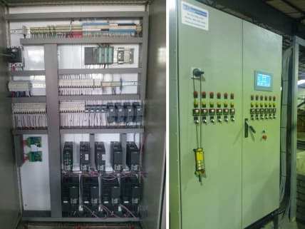
AUTOMATING ALL LINE FUNCTIONS
During the plating process, a number of key parameters have to be managed. In a manual operation this requires careful oversight and continuous attention. On a busy line operators will be making regular adjustments to their solutions and ensuring that they are constantly aware of panel readings. Today, every function of the plating process can be automated. This includes:
Current control to manage the specified amps per square decimetre per jig or barrel load. This is often achieved by barcoding of the jig or barrel with a job identification number that is scanned to preset the rectifier accordingly.
Temperature control to manage all heated process tanks within a narrow temperature band.
Level control of heated solutions.
pH control of plating tanks
Additive control to manage consumption of additives such as brighteners, levellers, stress reducers in tanks that require such additions.
Circulation/Filtration monitoring based on internal pressure of the filter stack.
Rinse flow control based on conductivity management.
THE TOTAL ELECTROPLATING LINE SUMMARISED
This brief overview shows that a plating line incorporating proper rinsing technology should consist of anywhere between 12 tanks for plating of a single metal up to 26 and more for a process like copper-nickel-chrome. These tanks must be laid out contiguously, edge to edge, so that whether we are considering a manual or an automatic process the movement of dripping jigs or barrels from one tank to the next does not allow the liquid contents of any of the processes to drip on the floor.
The overall management of a plating line is exacting, and this brief overview can only paint a broad strokes picture. A plating line is a big investment and we believe that no company should embark on such a project without being appraised of everything that is involved.
On the other hand, if a plating facility is justified, and is installed in accordance with modern best practice, then nobody who has a lesser facility will be in a position to compete on price or quality. Dedicated plating lines designed to cope with a range of components peculiar to a particular company will reap rewards for their owners. No commercial jobbing shop will be in a position to offer perfect work to specification, on time and repeatedly to the same standards as an in-house operator with a purpose designed facility.
The more tanks that are necessary, the more peripherals such as heaters, heater controls, circulation pumps, filtration units, extraction units, etc. will be needed.
So if you are evaluating your requirement in terms of either expanding an in-house plating shop, or building one from scratch, then the team at Accurate Automation and Consulting is standing by to give you no-obligation advice. Call us or email us today. Visit our Contact Page!
WHAT DO WE MEAN BY THE TERM ELECTROPLATING?
Electroplating describes the process of coating one metal with a thin coating of another by means of an electrolytic cell. The metal item being coated is the cathode in the cell and is often referred to as the "workpiece" or simply "the job". It is the base material or the substrate onto which the coating is deposited. The plating cell is described in more detail further on.
Corrosion prevention is not the only use for electroplating. Conferring the desirable properties of one metal onto another may include attributes like surface hardness, conductivity, solderability, or indeed beautification. Apart from steel, several metals are coated. This includes items fashioned from copper or brass as well as zinc die-castings and more. Apart from zinc, surface coatings include copper, nickel, brass, chrome, tin, silver and gold. An example of a predominant plated finish is the layered copper-nickel-chrome sequence used in the automotive, hardware and furniture industries amongst others.. Numerous examples exist of metals being used as a single deposit, or in combination to achieve specific outcomes.
A solution containing a water soluble chemical compound that will provide the desired metal ions for the plating process - for example copper sulphate when plating copper, nickel sulphate when plating nickel and so on.
The anodes (the donor metal immersed in the solution) and cathodes (the item that is receiving the metal deposit in the solution). In a basic configuration, anode bars will be positioned on both sides of the tank, and a cathode bar in the middle. Anodes are suspended on hooks from the anode bar and immersed in the plating solution. The items to be plated are suspended from the cathode bar, either on purpose designed hooks or in a bulk plating vessel, known as a plating barrel (described further on in this text). The anode bars are connected to the positive terminal on the rectifier while the cathode bar connects to the negative. Items suspended on the cathode bar and dipping into the solution complete the circuit between positive and negative and when current is applied, the plating process commences.
Accurate Automation and Consulting has built many of the largest and most modern automatic electroplating plants in South Africa. Whether you are new to electroplating and researching installing a plating facility for the first time, or whether you are looking at upgrading your facility, call us first. Once you've talked to us you will be ideally positioned to make the right decision. In this business, wrong decisions can lead to spectacular losses. We've seen it all before and our mission is to ensure that anyone making such a big commitment is fully appraised of all the relevant facts. For the newbies to electroplating out there, we take the liberty of providing a brief overview of what is involved with this process.